INDUSTRY NEWS
Thruster design for a contemporary unmanned underwater vehic
From the point of view of the physics of carrier propulsion, an unmanned underwater vehicle (UUV) is little different from a ski boat or a tanker. It uses a navigator-thruster-drive system model, which converts drive energy into thrust through the thruster in order to propel the vehicle into motion. The basic principle of thrust balance and motion is common to all three types of carrier, i.e. rotational energy is converted into axial thrust by the thrusters, the central component of the system.
The thruster designs for the different types of vehicles differ based on the design constraints and objectives specific to the respective mission of the vehicle. For example, a ski boat may require high thrust at towing speed and be willing to give up potential top speed to achieve this mission requirement; its gear ratios and thruster characteristics are designed for this purpose. For maximum economic return, a tanker may need to achieve maximum efficiency at 'economic speed'. Alternatively, it may additionally limit emissions or fuel consumption, which requires compromises in propulsion design.
Subsea vehicles have their own set of propulsion design requirements, taking into account the various tasks involved, such as battery life (or maximum distance operated at battery capacity), maximum diameter, minimum operating speed, whether to use a deflector propeller from a hydrodynamic efficiency or safety point of view, but also to ensure that noise can be reduced and data collection tasks can be carried out quietly. These design requirements were the thinking behind DD's design work for the UUV thruster, which came from a successful design project and was developed during an in-depth communication of design requirements and information with the client. The Vessel-Thruster-Drive model is a good framework for such design discussions.
Voyagers
A typical UUV is a gyroscopic shape (also known as an axisymmetric form) which has a nose, body and tail. In order to maximise the internal volume of the assembled device, some navigators have very short heads and tails. As you might expect, such a head inevitably causes an increase in drag, and also a loss of propulsive performance due to the fact that the fluid enters the propeller not axially but at a certain slope. The balance between the different drag components, such as hinged or pressure drag and frictional or viscous drag, is part of our job and often the desire to get the smallest drag to volume ratio is often not fully achieved. What we really want is the smallest power-to-volume ratio, and the geometry of the wake can greatly affect the ability of the thruster to convert gyroscopic energy into effective axial thrust.
For this reason, many thruster design projects start by using software to predict the drag and hull-propulsion coefficients (associated flow fraction and thrust reduction) of the vehicle.
A unique submersible module provides powerful predictive analysis capabilities for torpedo-based UUVs
Drive
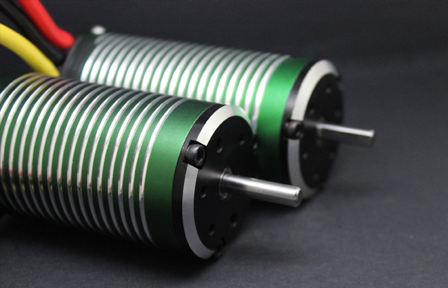
The counterpart to the thruster is the drive unit, which is usually an electric motor. The electrical characteristics of the motor vary, but the key data for the design of the thruster is the curve of the mechanical output power on the rotating shaft in relation to the speed. The peak of the input electrical power is important and, of course, corresponds to a certain operating limit. We use the motor efficiency curve to describe the input electrical power, which helps to answer the following question: If maximum battery life is the highest priority, what is our optimum target speed range? On the other hand, the power versus speed curve of the spool will tell us the speed corresponding to the maximum possible power and, by extension, the speed corresponding to the potential maximum propeller thrust and navigator speed that can be obtained.
As can be seen from a typical motor spindle power, motor efficiency versus speed curve, the highest possible power rarely (if ever) occurs at the highest motor input efficiency. Therefore, we often have to define the design speed point as a compromise between providing a higher output power and providing the best motor efficiency.
Related to every discussion of motor-driven UUV is the fact that the shaft speed is almost always too high for optimum propeller operation. It is common to see some form of transmission for optimum thruster performance or to accept that the thruster may operate at mediocre efficiency.
Thrusters
You will notice that the term used here is "thruster" rather than "propeller". This is to reinforce the concept that the duct and propeller (found on most UUVs) are an interactive unit, i.e. the thruster. Propulsion is designed to find the best combination of propeller and duct, while keeping track of their interactions. In other words, you must use a design tool that has this interaction analysis. A common goal in all UUV propeller design projects is to develop a geometry that produces the highest thrust-to-power ratio (efficiency), which we achieve through extensive and proven testing. Often the influence of external design drivers can make a successful UUV thruster design challenging. For example, the rotational speed may be too high (as described above), geometric constraints may limit the maximum diameter, or they may influence the design by considering the slope of the carrier wake.
It is significant to take a moment to mention UUV propeller manufacturing. There has been much discussion in the media about 3D printing of propellers. While this may be attractive from an economics and capacity point of view, we must be careful that performance is not compromised by inappropriate surface texturing (which has a huge impact on the smaller propellers on most UUVs), fatigue strength failure or hydraulic elastic buckling in the blades.
In addition to these practical design considerations, one of the most interesting contemporary design drivers is radiation noise. As part of a wider sustainability programme, DD has proven expertise in propeller hydroacoustics (capturing noise and vibration). This knowledge is also available to other shipbuilding designers and engineers as our tools develop new hydroacoustic properties. The sensitivity of projects to noise is always part of the discussion with our UUV propulsion design engineering customers.
All hydroacoustic excitation comes from mass fluctuations (periodic movements of the fluid mass). Propeller-driven hydroacoustics are usually caused by the vibration of the propeller in the low-pressure area as it turns in and out of the "masked" area (e.g. behind the struts or control fins). Part of this fluctuation is simply a change in the direction of flow around the blades due to changes in inflow, this change in flow direction is more importantly caused by the rapid expansion and rupture of the blade vacuoles. Each of these influences is assessed as part of our thruster design work, and the effects are mitigated by changing the profile of the blades and their camber distribution as required.
Excessive hydroacoustic excitation and transmission can also be aided by a creative duct design. Using our background of experience in duct performance simulation, we can consider whether a particular noise suppression duct geometry will provide the necessary suppression and any loss of propulsive efficiency that may result.


