COMPANY NEWS
Making an unmanned ship from scratch - a guide to the overal
foreword
First of all, if an unmanned ship is to be "unmanned", it must be able to run by itself; to run by itself, it must know its own GPS coordinates and its own attitude. Just like an airplane, it is possible that the value of an airplane at a certain latitude and longitude of the earth is the same, but one airplane is flying to the sky (Upwards), and the other is diving to the ground (Downwards), which needs to be determined; so As a result, there are actually 6 degrees of freedom for an aircraft: 3 degrees of freedom for coordinates in three-dimensional space, and 3 degrees of freedom for rotation around three axes in three-dimensional space. Combining these six degrees of freedom , we can only be accurate until the current specific state of an aircraft, which is called "Attitude" in our jargon.
In order to control the current attitude of the vehicle, it is necessary to measure the attitude data well, and then control it.
The process of using various sensors to measure the current attitude is called "attitude solution" in jargon.
For our ship (similar to the car), the ship will generally not go upwardsdownwards like a plane, otherwise it will either capsize or a spaceship "ship". At present, although these two angles are calculated in my program, they are not actually used. Because it is a boat after all, it generally drives smoothly in the water. If the range of the two degrees of freedom of roll and pitch varies greatly, then it is not far from capsize. . If it does appear, then there is no way, run an unmanned ship and encounter a tsunami, turn it over and turn it over. However, these two angles can be used to develop a self-stabilizing system against wind and waves. This is temporarily held down, continue to introduce down.
So we only consider whether the bow is left or right. The angle of this deviation is called "Yaw" in jargon.
Well, if our ship knows the current four degrees of freedom it can navigate. This paper mainly explains from the following dimensions:
sensor
filtering algorithm
system structure
route plan
About the sensor
Generally, to develop an unmanned vehicle (not limited to boats), to control it well, at least the following sensors are required:
GNSS positioning system (typical: Ublox M8N)
Gyroscope (Typical: MPU6050)
Accelerometer
(Optional) Magnetometer (Typical: HMC5883)
Of course, if you need to make unmanned ships more intelligent, you can consider adding millimeter-wave radar, vision systems, etc. for automatic obstacle avoidance. These are future expansions, so let's start with the basics.
Starting from the GNSS module:
Generally speaking, GPS is just the old and beautiful positioning system. In fact, there are Beidou, Galileo in Europe, and GLONASS in Russia. These are collectively called GNSS, Global Navigation Satellite System. Full name. Well, the GNSS receiver is installed on the boat, and it can output the latitude and longitude of the current location of the receiver module. However, different positioning systems are based on different coordinate systems. GPS is based on the WGS84 coordinate system, and Beidou is based on a set of our country's coordinate system. Do not use latitude and longitude values indiscriminately, otherwise the deviation will be as bad as Hawaii.
The most used GNSS module is the Ublox M8N. Some people said that this GNSS module is not good in the previous competition, but in fact, the M8N is very easy to use. Many cars use it, and many cars are not necessarily equipped with positioning systems. Catch the M8N (priced at 200)
The only problem is that fakes are rampant, and my introduction above is all based on the fact that we bought a genuine product.
Well, the latitude and longitude in a certain coordinate system is obtained, and there is still one last degree of freedom: Yaw (yaw angle), which is the pointing of the bow. In order to obtain Yaw, there are two ways:
1. Utilize GNSS. Let the boat take two steps forward after launching, and we can use the principle of connecting two points to form a straight line to know where the bow is facing.
2. Use a magnetometer. Some GNSS modules have a line of small words written on them: with compass. This compass refers to the magnetometer, which is actually an electronic compass! Magnetic data on three axes is collected using the Hall principle. The problem is: it doesn't know what is geomagnetism and what is artificial magnetism. If you put the unmanned ship next to two big magnets, the ship will have to collide in minutes. This is one of the problems. The second point is that high-frequency digital communication on our circuit boards, such as the IIC protocol, also scatters magnetic forces. Affects the navigation of the ship. For this reason, magnetometers are more controversial. My idea is to combine the magnetometer and GPS, but how to combine it will be done later. The most important thing is to set up the framework first.
2. Speaking of gyroscopes:
The basic function of the gyroscope is to measure the angle. You can simply think of it as a compass - but please note that the principle of a gyroscope pointing has nothing to do with magnetism, it is measured using the conservation of angular momentum. As an analogy, imagine you have a gyroscope in your hand, and when you calibrate it, you point its needle at your door (it doesn't have to be true south and true north, which is a significant difference from a magnetometer), and then If you go out and run around your house, you will find that the pointer of this gyroscope always points to your door - this way you can measure the angle between your door and your door when you move.
In this way, with the gyroscope, you can monitor the angle between the vehicle and the set origin when it moves in real time. But there is a potential problem with gyroscopes: the values it measures are drifting. That is to say, the measured angle value will become more and more inaccurate over time.
In addition, we know that the accelerometer can measure the acceleration of the movement of the object, and then the value of the displacement can be obtained by integrating the measured acceleration value twice each time. Therefore, simply using gyroscopes and accelerometers, we can make an inertial navigation system that does not require any other reference frame!
About Filtering Algorithms
The sensor introduction is complete. Assuming that we have made the sensor, and then read the data, we directly use the read data to control the unmanned ship. What you will see is: put the boat in the water, turn it on - why does the boat keep shaking?
The reason for this is that the data directly obtained by the electronic sensor is very noisy and needs to be filtered. For example, the yaw angle of the ship's bow read by the sensor in one second is 30 degrees, the next moment may be due to sudden interference, the reading becomes 60 degrees, and the next moment returns to normal 30 degrees.
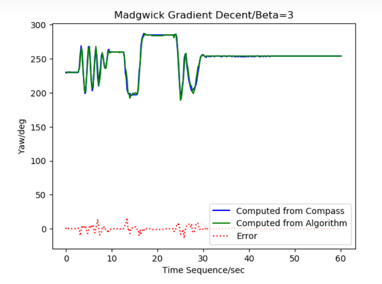
Here comes the magic filtering algorithm. Input the noisy data in the sensor data and it will give you filtered output that is very close to the real data. Common filtering algorithms are: Kalman filter, Madgwick gradient descent algorithm, in addition, we can also use complementary filtering.
Taking complementary filtering as an example, complementary filtering means that the error of the accelerometer is a high-frequency error, and the error of the gyroscope is a low-frequency error. Well, since the two sensors are different in what they are good at, let's complement their strengths - using the gyroscope to correct the high frequency error of the accelerometer, and the accelerometer to correct the drift (low frequency error) of the gyroscope. The basic core ideas of other attitude solving algorithms are similar.
But be careful! The complementary filtering algorithm can only correct the values of the gyroscope and accelerometer. If you have a magnetometer on your vehicle, this algorithm cannot filter!
It is recommended to use Madgwick's gradient descent attitude solution algorithm, which is very fast and occupies less resources on STM32; however, since Kalman filtering involves matrix operations, if it is solved on STM32, it will Seriously degrade system performance.
About the system structure
First of all, the mature unmanned ship system generally adopts the architecture of the upper computer + the lower computer.
The so-called host computer, taking the Raspberry Pi as an example, is similar to the human brain and is used for interaction, synthesis and advanced operations;
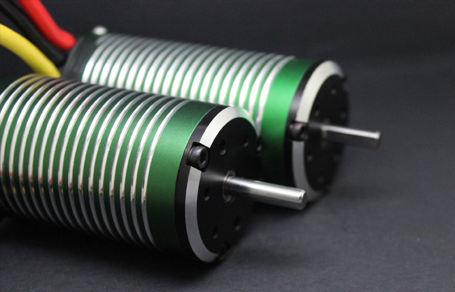
The lower computer generally uses an embedded chip such as STM32, which is similar to the human cerebellum, responsible for motion control, and directly issues instructions to peripheral devices such as motors.
The unmanned cars built in the smart car competition in colleges generally have only one embedded chip, because the unmanned cars made by students are generally simple in structure and not complicated in function, and do not involve too many complex operations and interactions. However, a mature unmanned ship requires users to directly debug in a remote way; and can obtain various sensor data remotely in real time, so it is best to be equipped with a host computer.
A simple example is that if you want to remotely control the computer of the unit to work, then the computer of the unit is a host computer; the printer of the unit is the lower computer; you can control the printer of the unit at home to print data, which is a simplified method of using the upper computer. process.
In addition, many functions can be easily expanded through the host computer. For example, the host computer of the unmanned ship project attached at the end of the article has added the function of voice prompting the working status of the unmanned ship through only two or three lines of code. If only the lower computer is used, the workload is very large.
There is another problem to note, that is, generally speaking, the stability of the upper computer is not as good as that of the lower computer, so it is necessary to do a good job in safeguarding procedures. For example: in the unmanned ship project attached at the end of this article, the control information of the remote control is fully taken over by the lower computer. That is to say, even if the upper computer hangs up suddenly during the automatic cruise, as long as the lower computer STM32 is online, then you can use the remote control to remotely control the vehicle back.
About Path Planning
With these, our unmanned vehicle already has the ability to drive remotely. If you need to add the automatic cruise function, you also need to add the part of path planning. Suppose you are given two latitude and longitude target points A and B, how to plan a route?
Well, the azimuth-coordinate conversion is used here, that is, with two GPS coordinates, you need to calculate the azimuth and distance between the two coordinates; with the azimuth and distance, you need to reverse Come and calculate the second coordinate based on the first coordinate point.


