INDUSTRY NEWS
What is the basic working principle of brushless DC motors?
The principle of the rotation of an electric motor
Let's start with the basic principles of electric motors. If you have the basics, you can skip it.
We all played with magnets when we were children. The opposite poles attract each other, and when two magnets come close together, they "snap" and hit each other.
Now suppose you are fast enough to hold a magnet in front of you and hook it wildly, then the other magnet keeps following you.
Your hand draws circles with the magnet and the other magnet follows you around in circles.

This is the basic principle of motor rotation. The only thing is that the "magnet" used in the front is not a real magnet, but a magnetic field generated by energising the coil.
1. Introduction to brushless DC motors
Brushless DC motors are known by the acronym BLDC (Brushless Direct Current Motor). The stator (the part of the motor that does not move) is the coil, or winding. The rotor (the rotating part) is the permanent magnet, which is the magnet . Depending on the position of the rotor, a microcontroller is used to control the energisation of each coil, so that the magnetic field generated by the coil changes, thus constantly hooking the rotor in front of it and making it turn - this is the principle of rotation of a brushless DC motor. Here's a little more depth.
2. The basic working principle of a brushless DC motor
2.1 The structure of a brushless DC motor
Let's start with the most basic coil.
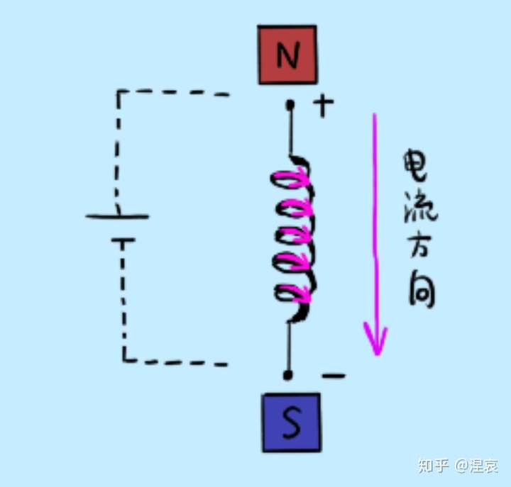
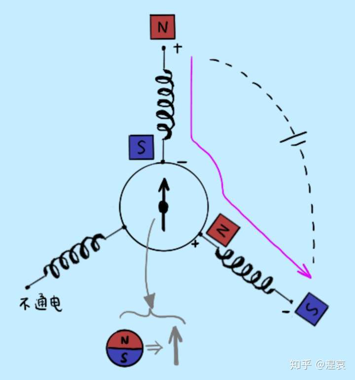
This is shown in the diagram below. The coil can be understood as something that grows like a spring. According to the right-handed spiral rule learned in elementary school, when current flows from the top to the bottom of this coil, the polarity at the top of the coil is N and the polarity at the bottom is S.
Get another one to make up the three-phase winding of the motor.
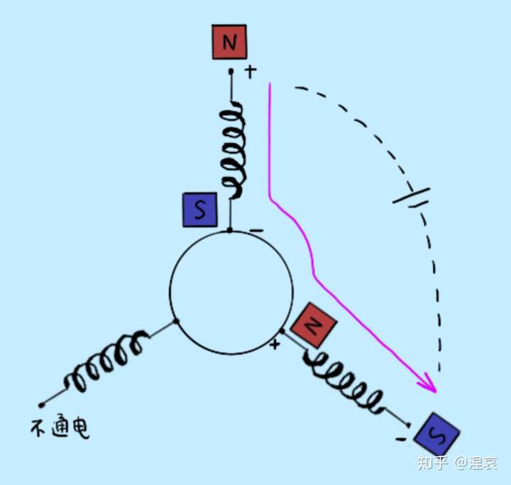
Together with a rotor made of permanent magnets, this makes a brushless DC motor.
2.3 The current commutation process of a brushless DC motor
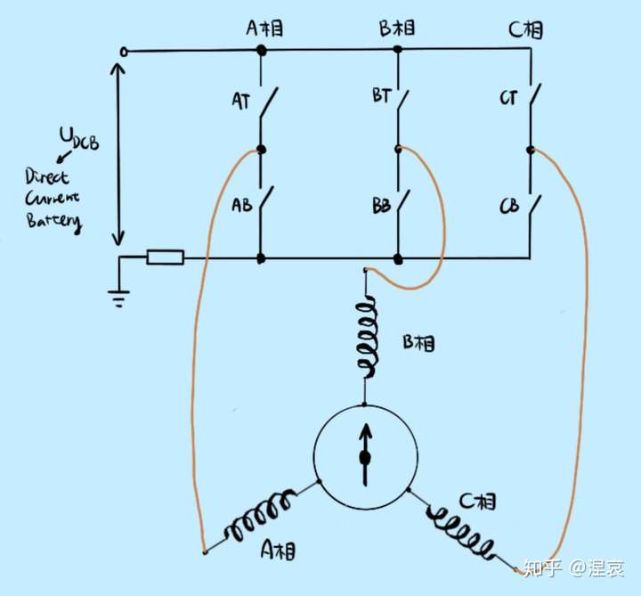
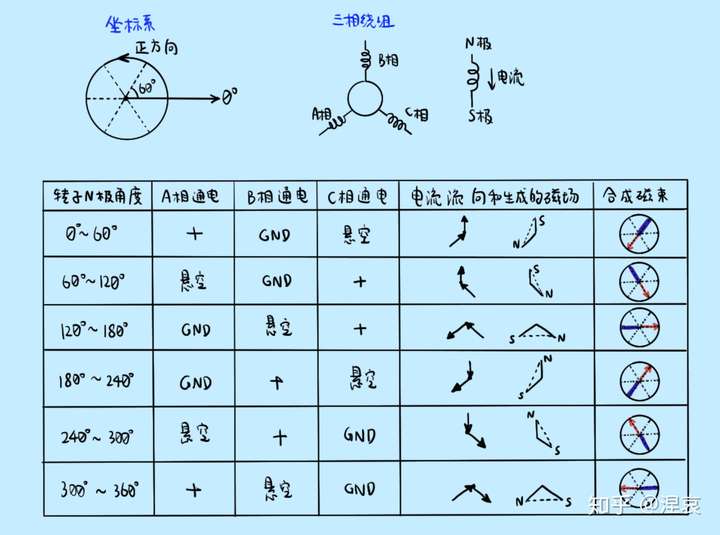
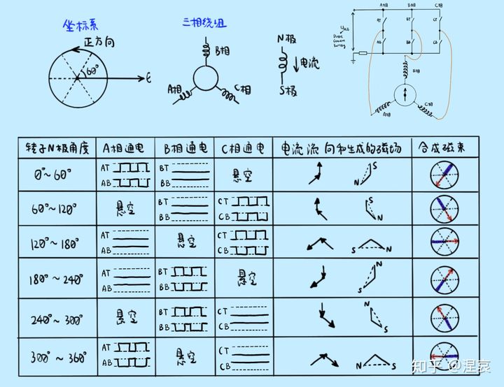
The timing of the "opening and closing" of the FET is controlled by the microcontroller. The most common method of current commutation is Six-step Commutation, which translates as "six-step commutation". Now build a coordinate system. The six-step commutation process is shown in the table below.
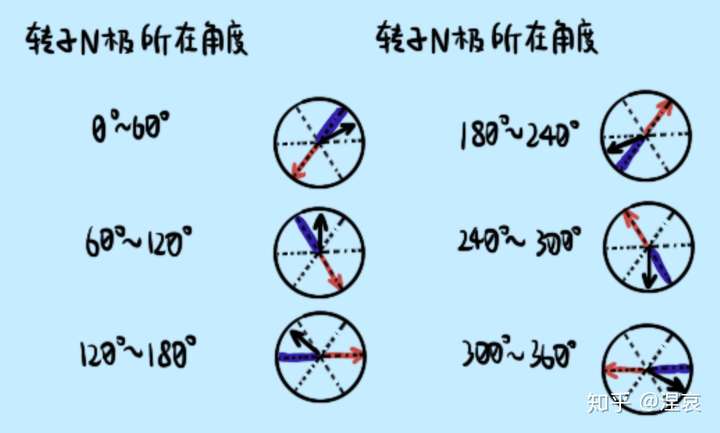
2.4. How does the rotor of a brushless DC motor turn?
By generating a rotating magnetic field with a six-step commutation, which is constantly hooked in front of the rotor. Just like the hand holding the magnet and drawing circles at the beginning of the article. If you look at the direction of the synthesised magnetic field and the position of the rotor, it is clear.
3. How do I determine the timing of the commutation?
As mentioned above, the key to controlling the rotation of the rotor is to wait for the rotor to reach the right angle and to commutate the current through the coil so that the direction of the magnetic field generated changes, attracting the rotor and causing it to rotate.
How do I time this current reversal? In other words, how do I know where the rotor is now? I know where the rotor is so that I know which two phases to energise.
There are many ways to determine the position of the rotor, either with or without a sensor. First of all, if you use a sensor, you can use a Hall Sensor.
3.1. Confirming the rotor position with a sensor
3.1.1. Hall sensors
Hall sensors detect changes in magnetic field strength by means of the Hall Effect. According to the left-hand rule learned in high school physics (used to determine the direction of force on a charged conductor in a magnetic field), in the circuit where the Hall sensor is located, the magnetic field deflects the motion of the charged particles and the charged particles "hit" the two sides of the Hall sensor, creating a potential difference. A voltmeter can then be connected to both sides of the Hall sensor to detect this change in voltage and therefore the change in magnetic field strength. The principle is shown in the diagram below.
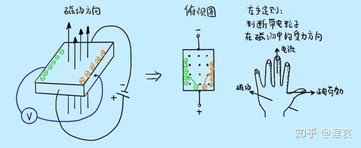
3.1.2. How do Hall sensors get the position of the rotor?
With a Hall sensor, the position of the rotor can be roughly known. Hall sensors are generally installed at 120° intervals or at 60° intervals. The following assumes that they are mounted at 120° intervals.
The output voltage of the Hall sensor is assumed to be high (typically 5 V) when the N pole of the rotor crosses the sensing area of the Hall sensor. The opposite is low.
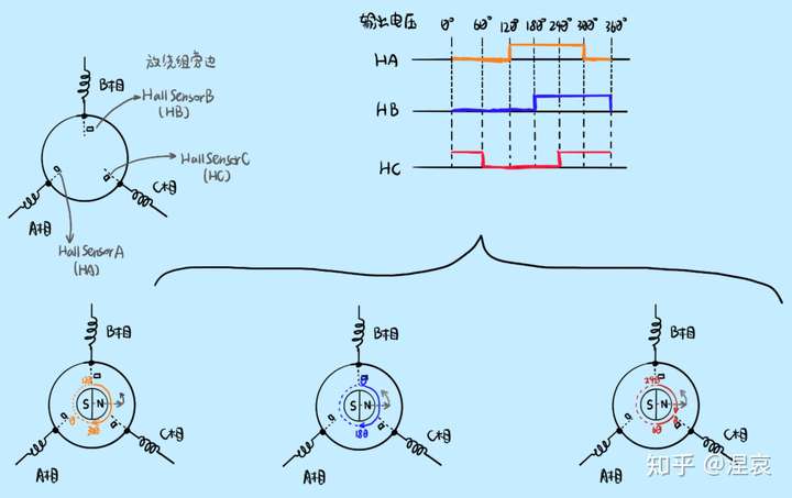
Depending on the levels of HA, HB and HC, we can know the angle at which the rotor is positioned. For example, if HA is high, HB is low and HC is low, we are able to know that the rotor is at an electrical angle between 180 and 240 degrees (the relationship between the electrical angle and the actual mechanical angle is described later). When using 3 Hall sensors, the resolution is 60 degrees of electrical angle. This means that I can only know that the current position of the rotor is within 60° of the electrical angle, but we do not know exactly how many degrees.
3.1.3. Relationship between electrical and mechanical angles
Although it is a bit odd to insert such a tidbit of knowledge here, I felt it was necessary because I felt it was not easy to understand at the time of learning. It might be better to explain it here with the example of the Hall sensor.
The mechanical angle is the angle at which the motor rotor actually turns.
The relationship between the electrical angle and the mechanical angle is related to the number of pole pairs in the rotor.
This is because it is the poles of the rotor that are actually attracted to the magnetic field generated by the coil. So for the control of the rotation of the motor we are only concerned with the electrical angle.
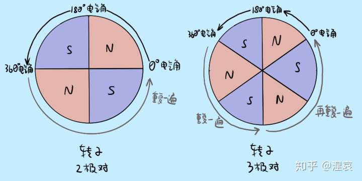
Electrical angle = number of pole pairs x mechanical angle
3.2. Method of estimating the rotor position without a sensor
This is a bit of a hole, so I'll skip this answer for now.
4. Speed and direction of rotation of a brushless DC motor
4.4. How do I control the direction of rotation of a brushless DC motor?
By changing the order of the current commutation. The direction of rotation is reversed by the direction of the combined magnetic field of the coils.
4.5. How can I control the speed of a brushless DC motor?
The higher the voltage across the coil, the higher the current through the coil and the stronger the magnetic field generated, the faster the rotor will spin.
Since the power supply is DC, we usually use PWM (Pulse Width Modulation) to control the amount of voltage across the coil.
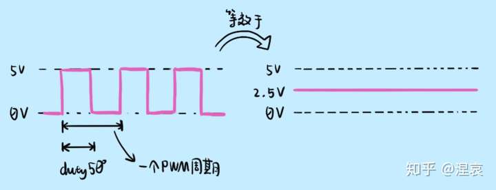
So when energising the brushless DC motor, the PWM generated by the microcontroller is used to constantly control the opening and closing of the FET, which can make the coil repeatedly in the state of power on and off, power on and off. Long power-on time (Duty large), the equivalent voltage at both ends of the coil is large, the resulting magnetic field strength is strong, the rotor rotation is fast; short power-on time (Duty small), the equivalent voltage at both ends of the coil is small, the resulting magnetic field strength is weak, the rotor rotation is slow.
The PWM waveform is connected to the Gate of the FET (gate), which controls the opening and closing of the FET. Assuming that the voltage on the Gate is high, the FET is closed and on; when the voltage on the Gate is low, the FET is open and not energised.
Furthermore, the upper and lower FETs on the same phase must be controlled by an inverted PWM waveform to prevent the upper and lower FETs from conducting at the same time, resulting in the same current going up and down without passing through the motor, causing a short circuit. The PWM waveforms controlling the FETs are as follows.
In summary, there are three keys to brushless DC motors.
1. The commutation sequence of the coil winding currents. The commutation sequence of the currents determines the direction of rotation of the magnetic field generated by the coils, and thus the direction of rotation of the rotor
2. Hall sensors or other means to estimate the position of the permanent magnet rotor, which is used to determine when the current is commutated
3. PWM waveforms generated by a microcontroller are used to control the timing of the motor windings to control the speed of rotor rotation
